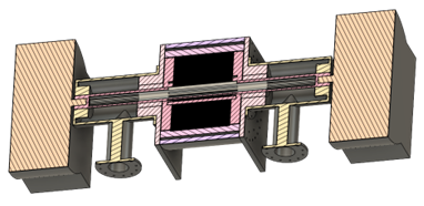
Pyrogen Energy Turbines
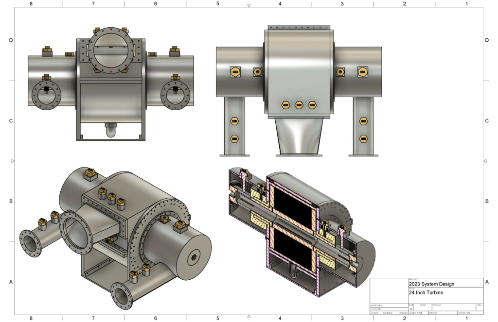
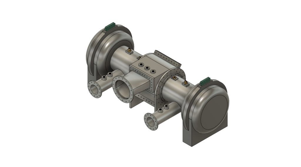
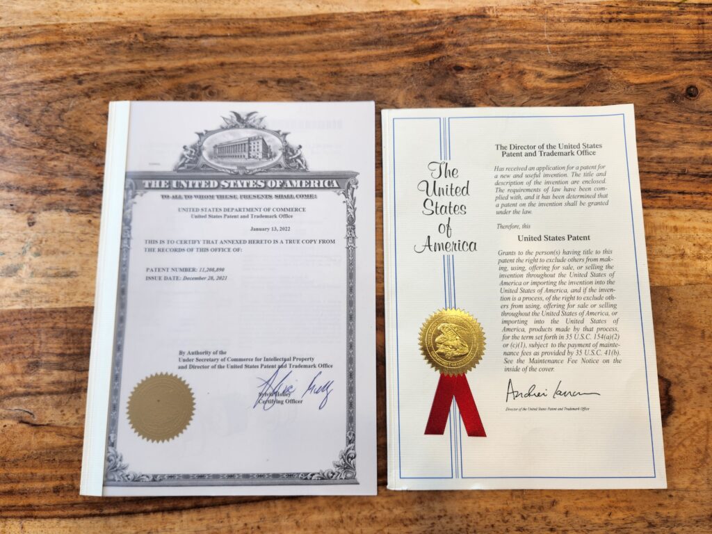
Pyrogen Energy has developed Tesla-based turbines alongside other technologies over the last 10 years. Technology development began with Bill Helton at Aurora Energy and Green Frog Systems before moving to Pyrogen Energy. Over the course of this history, we have developed patented technologies from hydrogen generation to turbines and waste-to-energy systems.
Pyrogen Energy is on a mission to define and refine a conversion technology that maximizes electrical output from its hydrogen production technology by harnessing available waste heat. Our business interests extend into many fields where this technology would be applicable.

The Pyrogen Energy Turbine is an adaptable, high-performance, hyper-efficient design that converts the heat component of a working fluid into mechanical work. The Turbine is made entirely from stainless steel and has been designed to use water and / or exhaust gases as the working fluid.
This is beneficial in many situations even where high-quality steam is not available. Water enters the turbine as steam and leaves as liquid. Any fluid within a wide range of pressures and temperatures (dictated by material properties) theoretically may be used in our bladeless disk turbines. This technology also can be used for removing waste heat from a system and using a refrigerant to absorb the heat causing the refrigerant to expand (i.e., increased pressure) and then convert that heat into rotational force. This allows us to use several different working fluids across a wide range of temperature differentials. This can all be done within in a closed- or open-loop system.
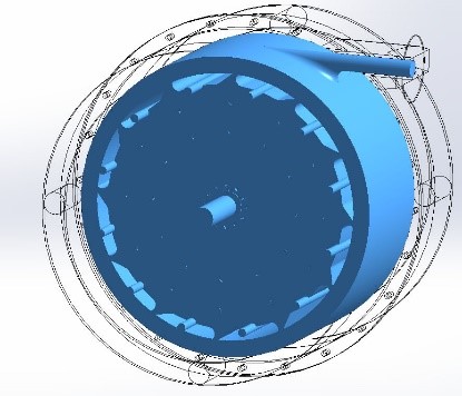
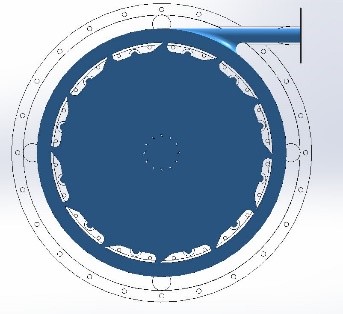
Volume of working fluid in turbine (blue)
The volume of the internal working fluid is shown in the image below. Steam, exhaust gases, or water / refrigerant may fill this area, either separately or in combination. Note the Venturi geometry controlling the gas flow between the concentric circles shown. As the RPMs of the turbine increases, gas flow increases towards the center of the bladeless disks. At lower RPMs, it tends towards the outer edges.
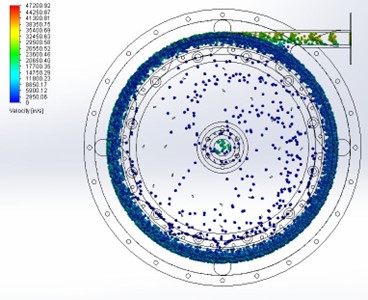
Low Flow simulation
of turbine
In this illustration, a lower flow rate is shown. Note the centrifugal force has a notable effect on the fluid, causing it to stay closer to the periphery. The efficiency in a lower flow system is approximately 60% compared to 90%+ in a high flow environment.
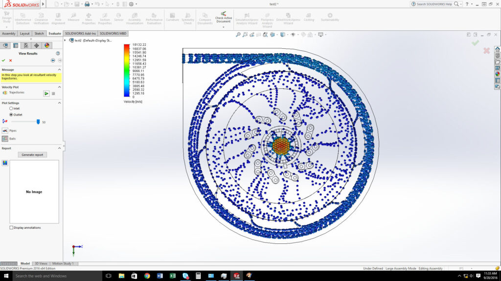
High Flow simulation
of turbine
The high flow simulation shown here indicates a higher flow over the surfaces of the bladeless disks. The lighter blue colors compared to the previous image indicate higher velocities within the flow. The local Coriolis effect is not as strong here due to the higher rotational velocity.
The turbine uses bladeless disks, utilizing the boundary layer effect. Instead of ramming air into a blade surface, the working fluid “sticks” to the surface of the bladeless disks. In this design, the fluid must find the path of least resistance and thus it spirals from the edge of the turbine towards the center, applying the internal energy (heat, pressure, and velocity) of the working fluid to the turbine surfaces. The bladeless disks are attached to a hollow shaft on either end, maximizing the useful surface area of the bladeless disks.
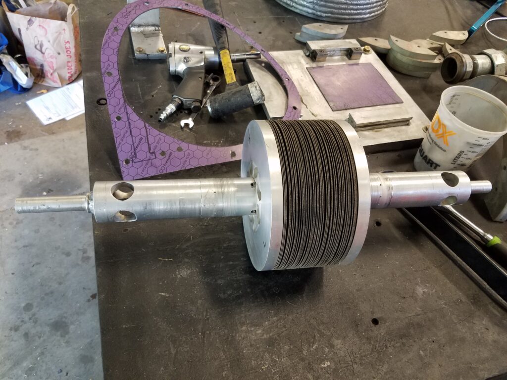
The proverbial heart of the system is a collection of these disks. Each disk is made of stainless steel and features tiny bumps to aid in the rigidity, precise spacing, and airflow as they work.
Turbo Generators
The power generation component is an important part of the system; it is basically a Pyrogen turbine and two core motors combined in one case.

Both motors are same output

Pyrogen Energy Turbine
The Pyrogen Energy Turbine is a prime mover. The turbine utilizes the boundary layer and adhesion principles like the original Tesla turbine with a few major changes. We utilize multiple entries, precise geometry, and a shaftless design that allows for less delta-V change in the working fluid. Unlike any other turbine manufactured today, this allows phase change of the working fluid inside the turbine, which delivers up to 30% more energy from the working fluid. Our design makes this achievable without destroying the internal structure of the turbine.
The rotating mass has approximately 180,000 square inches of surface area and two internal air seals. It is supported by two high-RPM, high-load air bearings. This is then flange-connected to the core generator motor to make up the turbo generator. The entire case is sealed and has flange connections to allow all of the condensate to be expelled to the condensate collection tank for reintroduction into the system.
